


Design bureauOur capabilitiesWe hope, this information has formed some notion of our capabilities, and would interest You. We shall thoroughly scrutinize any cooperation offers. We accept orders for development and supply of prototype models of high-speed torque two and three axis motors and their control systems. Upon testing, arrangement of serial production or documentation hand-over to the customer is possible. The term of creating a prototype model, by Your requirements, is from one to three months, depending on the task complexity and the available scientific, technological and practical reserve.
1. Micro-motor dental drillsPortable micro-motor dental drills are created based on specially designed high-rev brushless electric motors. One of our dental drills design peculiarities - absence of windings and brush contacts on micro-motor rotor, thanks to which coal dust soiling of the intra-cavity is excluded, high dependability and longer operational life are provided for. In the micro-motors, high quality bearings from NMB company are used, which do not demand greasing and maintenance during the whole service life. New magnetic system and micro-motor winding scheme combined with modern materials and technology have secured a high specific capacity of the device, allowed the energy consumption and heating cut down. Rotors dynamic balancing, reached on modern equipment, makes the micro-motor operation silent even at threshold rotation frequency. Appliances were created by two modifications– “D&T-20” and “D&T-80”, the configuration of which includes a micro-motor with a stand, control unit and a sealed foot switch. “D&T-80” dental drill is designed for mechanical processing of metal, ceramics, stone, plastics, bone and other materials with burs, fraises, drills, disk saws, grinding and polishing wheels. “D&T-80” micro-motor (Pic.1) is supplied with collet mechanism for installation and fixation of changeable tools, having back end standard bore diameter 2.35 mm. Rotation beat of a tool installed in the shaft collet does not exceed 0.02 mm. In idle mode, when the tool is not fixed in the collet, shaft rotation is impossible. Tool fixation and release are carried out by the turn of the micro-motor sleeve holder. Main “D&T-20” dental drill designation is applying therapeutic procedures and operations in stomatology. Micro-motor of “D&T-20” (Pic.2) is equipped with a device for mounting standard straight and angular dental attachments. Micro-motor includes a spring-loaded stop, preventing spontaneous attachment disengagement. “D&T-20” can be also used for executing engraving or other works at materials processing, similar to “D&T-80”. Electronic control unit provides contactless rotor rotation in the straight and reverse directions, rotation frequency stabilization at external loading action, rotation frequency adjustment and digital indication, and also – rotor advanced dynamic brake at power outage. Micro-motor can be activated as by foot switch, as by a switch on the panel unit. Control unit can provide micro-motor operation in lowered capacity mode (30%) at the cost of limiting the rotation torque. Such function is necessary at executing some types of dental and therapeutic works. Besides, overload protection, e. g. at the tool jamming in the appliance, is implemented in the control unit. The design is protected by the patent of Ukraine № 53776. “D&T” dental drills have the Certificate of State Registration as medical purpose goods. Main characteristics of the dental drills are given in Table 1. Table 1.
2. Joints surgery sagittal saw
Electronic control unit is placed in the micro-motor body-frame and handle. The saw intra-cavity is protected from penetration of moisture into it. The issue of sealing the point of exit of the moving shaft from the body-frame is solved with the help of slide bearings with Teflon coating from “SKF” company (Sweden). Characteristics of the saw are given in Table 2. Table 2
Sagittal saw has successfully passed the tests at the time of orthopedic surgeries. Licensed sale of the technical documentation is a possibility.
3. Vibration massager
Used for micro-polishing of the skin, therapeutic and cosmetic massage, and also for treating post-surgery stitches. Technical characteristics of the massager are given in Table 3. Table 3.
4. Valve electric drive for geophysical instrumentsThe drive is designed for shifting the movable elements of the instruments submerged into bore wells, to the depth of up to 5,000 m, in high temperature conditions of up to 175оС and pressure of up to 1,000 atm. The micro-motor is placed under a protective cover, and its cavity is filled with IPM-10 type lubricating oil. Technical characteristics are given in Table 5. Table 5
5. Torque motors of radial and end typesDesigned to control the angular location of the tracking systems elements. MD designs are produced adapted to the general scheme of the instruments. Number of winding phases and polarity are varied depending on initial data. Shaft torque value is from 0.005 to 10 Nm. Brushless analogues of series DM motors can also be designed.
6. Two-axis torque and scanning systems with a single rotor (DEM).ПDesigned for two-axis control of the elements moving around two mutually orthogonal axes in the torque or scanning modes. Provide highest specific characteristics (Table 7) among any other systems, producing two-axis turn of the moving elements. Pic.6 – DEM -0.1 drive. Pic. 7 - DEM-2 drive. The characteristics are given in Table 7. Table 7.
7. Three-axis torque driveDesigned for three-dimensional orientation of various application objects with a possibility of rigid fixation of an object in the desired position. Primary designation of the development – communications satellite solar batteries orientation. No analogues in the world. Main characteristics are given in Table 8. Table 8
8. Small-size two-axis gyrostabilizersDesigned for control of angular position of receiving optical or radar installations located directly on the stabilizer rotor. The electromechanical part of the device includes a rotor, excited by permanent magnets and installed in three-axis suspender and a system of stator windings providing own and precessional rotor movement. Control unit provides the start and acceleration of the rotor, rotation frequency stabilization and control of precessional rotor movement in the tracking mode or putting it in the angular position. Precessional movement mode is provided due to interaction of rotor and stator fields. Use of separate moment detectors is not needed. Gyroscopic stabilization of the device is provided thanks to total kinematic moment of the rotor and the receiving device, rigidly connected with the rotor.
9. Small-size two-axis deflecting systemsDesigned for optical radiation scanning mode operation in medical, thermal imaging and measuring equipment. Includes a deflector mounted on elastic two-axis suspender, equipped with a magneto-electric drive. Miniaturization of the scanning device is reached by way of combining the advantages of two-axis electric drive (see p.7) and two-axis suspender of “cross hinge” type. The advantages of the elastic suspender are the absence of free plays and dry friction, high axial stiffness, small dimensions and the possibility of its adaptation to electric drive design. The device provides for a controlled element deflecting in any direction from the equilibrium position within the limits of elastic deformation of the suspender elements. Materials and geometry of the elastic suspender provide for the constancy of its roll stiffness in the whole range of bend angles and the linearity of deflection angle dependence from the applied deflection moment. With the help of control wirings, practically any scanning principle can be implemented: circular, spiral, saw-like, random, etc. In such a device the task of the mirror positioning is also solved easily enough. Scanning in resonant mode is also possible.
10. General purpose foot button switch
The switch is designed for bridging nonbearing electric circuits of direct and alternating current. Includes a contact group located inside a dielectric protective case with elastic rubber cap. Protection class - IP31. The switch is exclusively dependable. Used for activating electric drives in most of “Eleron”, SPF, designs of medical and general technical applications.
|

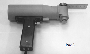 The saw contains a mechanism of converting micro-motor rotor revolutions into vibratory motion of a cutting tool. The saw is equipped with a swivel head for changing vibration plane of the cutting tool and with a mechanism for its quick replacement and firm fixation. Mounting seat for the tool assembly fits the saws from “Stryker” company (USA).
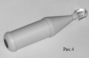 Vibration massager represents a micro-motor rotary type drive with internal flexible coupling. Replaceable massage attachments are installed on the shaft’s exit end. Control winding is connected to an adjustable alternating voltage source or network adapter. At configuring the appliance with a control unit, vibration frequency and amplitude adjustment of the working element is carried out. The appliance operates practically without noise.

Created by idg.net.ua
![]()